Technical Description of the Arduino Uno board Rev. 3
Microcontroller
Written by David Diop
The City College of New York
Author Note:
This paper was prepared for English 210, taught by professor Susan Delamare
Table of Contents
Abstract ……………………………………………………………………………………. p. 3
Introduction………………………………………………………………………………… p. 4
Background …………………………………………………………………………………p. 4
Arduino Parts and Functions ………………………………………………………………. p. 5
- Power Connector ………………………………………………………………. p. 5
- USB Port ………………………………………………………………………. p. 6
- Reset Button …………………………………………………………………… p. 6
- LEDs …………………………………………………………………………… p. 6
- Pins ……………………………………………………………………………. p. 7
- Microcontroller ………………………………………………………………… p. 8
Conclusion …………………………………………………………………………………. p. 8
List of Illustrations ………………………………………………………………………… p. 9
References …………………………………………………………………………………. p. 10
Abstract
This paper is a detailed description of the design and functions of the Arduino Uno brand, Rev. 3 microcontroller board. It covers the history and function of microcontrollers, as well as the specific parts and uses of the Arduino Uno board.
Introduction
A microcontroller is a small computer that is embedded into an electronic system. Microcontrollers are programmed to automatically perform a single specific task, with the aid of components including sensors and actuators. Sensors are devices that collect input from the physical world. They include things such as cameras, microphones, buttons, switches, etc. Actuators are devices that perform an action in the physical world. They include things such as speakers, motors, screens, lights etc. All three types of devices generally work together by first collecting data from the physical world, then sending that data through a program on the microcontroller, and finally performing an action based on the result. These kinds of systems are incredibly common, as microcontrollers are embedded in devices all around you. They can be found within remote controls, microwaves, TVs, toys, and basically any device that isn’t classified as a full computer. Microcontrollers were first introduced in 1971, with the TMS 1000, which was developed by TI engineers Gary Boone and Michael Cochran (Augarten, 1983). Today, it would be difficult to imagine life without these little devices.
Background

Figure 1 The Arduino Uno Board,
Image retrieved from: https://store-cdn.arduino.cc/usa/catalog/product/cache/1/image/500×375/f8876a31b63532bbba4e781c30024a0a/a/0/a000066_front_3.jpg
The focus of this description, the Arduino Uno, is a commercial microcontroller. With its open-source IDE (Integrated Development Environment: Software used for writing programs), and easy to use hardware, it’s designed to make programming and electronics more accessible to those who lack a background in the field.
This product is often sold in kits that contain not only the device itself, but a plethora of peripheral devices, wires, and other tools needed to assemble electronic circuits. These circuits may range in design and function, from the simple to the complex, and always have the Arduino at their heart. This creates a platform for people of all demographics and skill levels, to create their own projects and learn more about technology on a fundamental level.
Arduino Uno Parts and Functions

Figure 2 The many parts of the Arduino Uno Board,
Image adapted from: https://www.researchgate.net/figure/Arduino-Uno-microcontroller-and-its-parts-12_fig8_311741962
The Arduino Uno is a 68.6 mm by 53.4 mm microcontroller board (Arduino Uno Rev 3, 2018), and is composed of many parts whose intricate connections make the device work. Although, like any electronic device there are many dozens of internal components working together to make it operate, this paper will only cover the most significant parts. These are the parts that distinguish the Arduino from other electronics and they include:
Power Connector
As shown in the above figure, this port lies in the lower left-hand corner of the board and supplies electrical power to the Arduino Uno. This is usually accomplished by plugging a loaded battery holder into the port.
USB port
This port allows the Arduino board to be connected to a computer. This connection can serve as an alternate method for drawing power, when the power connector is not in use. This port also serves as the means for uploading code onto the microcontroller.
Reset Button
In the upper left-hand corner of the board, lies this button which, as indicated in its name, resets the microcontroller to its original state, thus deleting any code that has been uploaded onto it.
LEDs

Figure 3 Some examples of common LEDs
Image retrieved from: https://www.superbrightleds.com/moreinfo/through-hole/rgb-fast-color-changing-led-2/1041/2504/
An LED (Light Emitting Diode) is an electronic component that emits light when an electric current is applied to it. As shown to the left, they basically serve as tiny light bulbs. They are a common type of actuator and are generally used to convey information from a device by flashing lights in different patterns and durations. Although the Arduino Uno is able to be connected to external LEDs through a circuit, it also happens to include a few that are built directly into the board.
- Pin 13 LED
This LED serves as one of the few actuators that are built directly into the board. The light can be turned on or off by whatever program is running on the microcontroller.

Figure 4 The Pin 13 and Power LEDs active
Image Retrieved from: https://forum.arduino.cc/index.php?action=dlattach;topic=84596.0;attach=10877
- Power LED
This LED’s only purpose is to indicate that the device has power.
Pins
To create circuits with the Arduino Uno, several pins are utilized. Pins are small ports through which power, input, output and communications connections are formed with external components and devices. A microcontroller can typically have from 6 to 60 pins, each with different functions and configurations (Igoe, 2016).
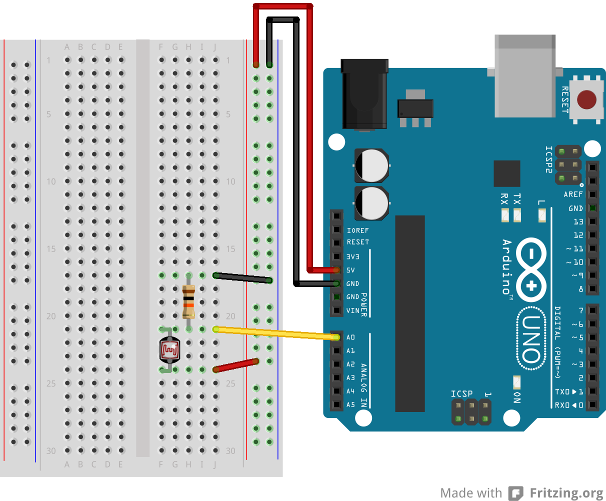
GND and SV pins
These pins are used to supply power to circuits formed with the Arduino board. As shown in the image to the left, these two pins serve as the positive and negative ends of the circuit, connecting the external components to the Arduino’s own power source.

Figure 5 The GND and SV pins supplying power to a simple circuit
Image Retrieved from https://www.arduino.cc/en/uploads/Tutorial/PhotoCellA0.png
Digital Pins
These pins, located opposite to the GND and SV pins, serve as a primary channel of communication between the microcontroller and devices connected to it. They can read digital signals from sensors and send digital signals to actuators. Whether each pin functions as an input or output channel depends on the program currently running on the microcontroller.
Analog Pins
These pins, located adjacent to the GND and SV pins, are designed to read analog input. Analog input is any information that isn’t represented as a binary sequence of 0s and 1s, as is standard for digital information. For example: in Figure 5, one of the Analog pins is receiving input from a photoresistor, a component that sends a different numerical value based on how much light is hitting its surface.
ATmega microcontroller
This chip is the heart of the Arduino. As shown in the image to the right it is one of the largest components on the board. It is the central processor that sends and receives signals to and from the pins, as well as runs the main program.

Figure 6 The ATMega microcontroller on the Arduino Uno Board
Image Adapted from: https://store-cdn.arduino.cc/usa/catalog/product/cache/1/image/500×375/f8876a31b63532bbba4e781c30024a0a/a/0/a000066_front_3.jpg
Conclusion
It would be difficult to imagine today’s world without microcontrollers, even though we normally don’t even notice they’re there. In fact, it would likely take quite some time to count all the microcontrollers you’ve used in one day alone. The Arduino, takes this often-underappreciated piece of technology and gives it the spotlight it deserves, by allowing any curious soul to experiment and create devices of their own.
List of Illustrations
Figure 1 The Arduino Uno Boars ………………………………………………………p. 4
Figure 2 The many parts of the Arduino Uno Board …………………………………. p. 5
Figure 3 Some examples of common LEDs …………………………………………. p. 6
Figure 4 The Pin 13 and Power LEDs active …………………………………………. p. 6
Figure 5 The GND and SV pins supplying power to a simple circuit ………………… p. 7
Figure 6 The ATMega microcontroller on the Arduino Uno board …………………… p. 8
References
Augarten, S. (1983). The Most Widely Used Computer on a Chip: The TMS 1000. (pp. 38).
Retrieved September 26, 2018, from http://smithsonianchips.si.edu/augarten/p38.htm
Arduino Uno Rev 3. (2018).
Retrieved October 12, 2018, from https://store.arduino.cc/arduino-uno-rev3
Igoe, T. (2016). Microcontroller Pin Functions (para. 2)
Retrieved October 12, 2018, from https://itp.nyu.edu/physcomp/lessons/microcontrollers/microcontroller-pin-functions/

This entry is licensed under a Creative Commons Attribution-NonCommercial-ShareAlike 4.0 International license.